
T1 Line Wiring Diagram
There will be main lines that are represented by l1, l2, l3, and so on. Some electrical engineers that are on here will also see :

T1 Wiring Diagram
Clearly the intended use of t1 was to bring in as many telephone lines using voice as possible through a digitized technique (pcm pulse code modulation).

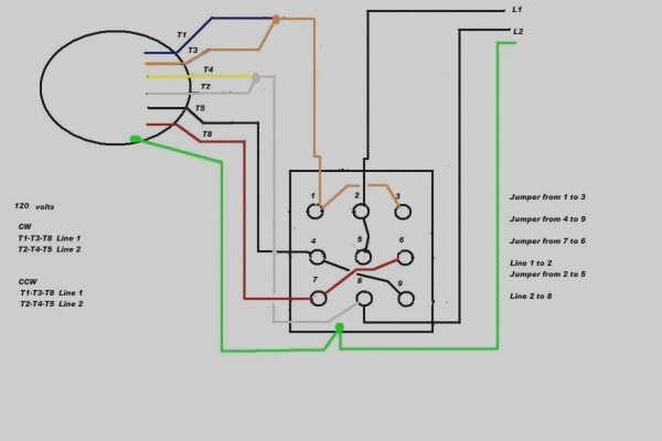
T1 line wiring diagram. T1 and t4 shall be assigned to the main winding and t5 and t8 to the auxiliary winding (if present) with the polarity arrangement such that the standard direction of rotation is obtained if t4 and t5 are joined to one line and t1 and t8 to the other.* the terminal marking arrangement is shown diagrammatically in fig. T1 = tap 1 t2 = tap 2 t3 = tap 3 (of a transformer secondary winding on the output reduced voltage side) L1 and l2 motor wiring.
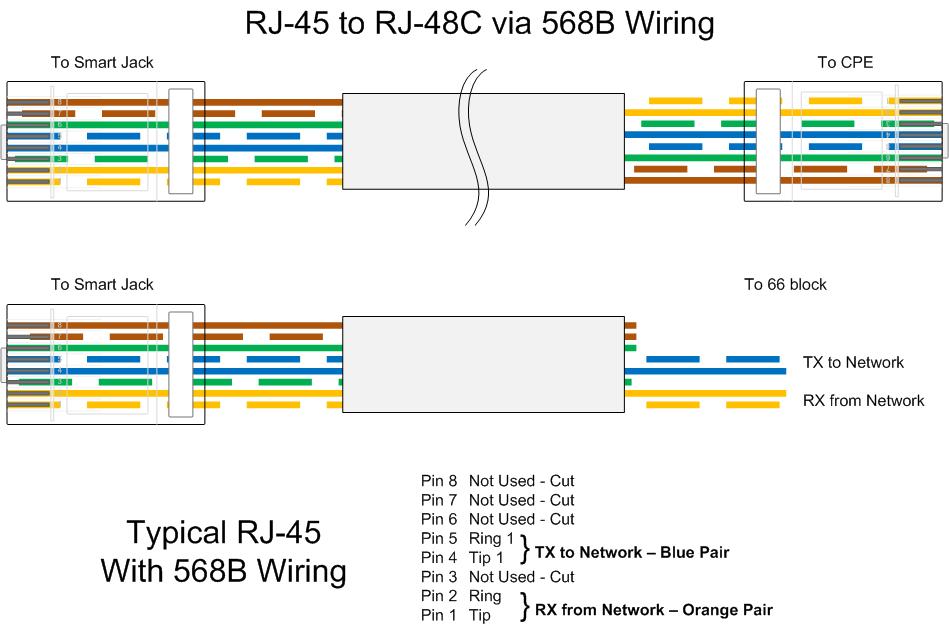
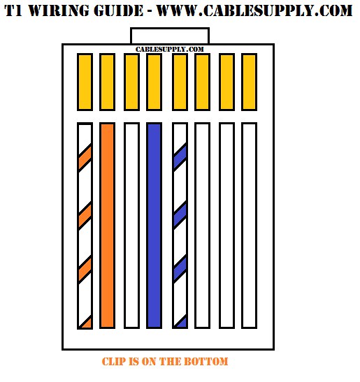
In models vfc063p, vfc084p, vfc100p, vfc200p, and vfc300p the thermal protector is in direct line with the power to the motor windings. Each lead may have one or more cables comprising that lead. In a 4 wire t1 configuration only 2 pr are used blu/bluwht and ong/ongwht.
If a thermal overload occurs, the. Save the diagram to your hard drive, remember where you put it! Beyond that just find an open 2 pare on your 50 pin trunk cable.
Shows a typical line or schematic diagram. Open the diagram on your computer with an image program. T1 t2 t3 2/ 4/ 6/ separate control remove wire "c" if supplied and connect separate control lines to the number 1 terminal on the remote pilot device and to the number 96 terminal on the overload relay l1 l2 l3 5 reverse 5 4 2 5 s.p.d.t.
The voltage between two lines (for example 'l1' and 'l2') is called the line to line (or phase to phase) voltage. T1 cable can be a rj48 or a simple rj 8 pin. Injunction of 2 wires is usually indicated by black dot to the intersection of 2 lines.
The advantage of this is the ability for the agents to use their own existing telephones as apposed to a stand alone system that requires analog headsets. T1= transformer 1 t2= transformer 2 t3= transformer 3 as i was trained in electrical and electronics before i went into bashing and denting other types of work. For field added limits, remove yellowjumper wire and attach between y and t1 on defrost control board.
According to earlier, the lines at a cat5 phone line wiring diagram signifies wires. Gas furnace s s y y2 g c u u a w2 w k rc r l/a e aux m36915 1 common optional. T1 t3 t2 yel/pnk blu/pnk yel/ blu brn/yel *hps blu/pnk cont 11 21 23 23 schematic diagram (ladder form) l1 *sr *sc h comp *st c f cap l2 5 2 1 *lps * ctd *dts *lls ifr thermostat indoor y g r r c external power.
In such case each cable will be marked with the. T4 and t1 pro wiring diagrams wiring diagrams 1 stage heat only: In the end the white/blue and blue pair of wires is your transmit ring and tip and the white/orange and orange pair of wires is your receive ring and tip.
Universal service order code (usoc): The t symbol designation refers to the terminal or termination, which in this case is a wire lead that. Depending on the correct wiring.
T1 t2 c y o o w2 r r dft e c y o w2 r e df1 df2 black yellow black reversing valve solenoid defrost control board note: Some of the fuse boxes pictured in the diagrams are. However, it does not imply link between the wires.
Be sure to keep the blu and ong pairs straight. L1 and l2 indicate that the motor voltage may be 240 volts. All wiring must be done by a licensed electrician.
Rvs 2 3 yellow black yellow red or red black black or black white yellow or terminal yellow black or gray wire cc. So i assume that 1 2 and 3 are t1 t2 t3 for the motor. Most heat only, gas or oil forced air systems do not use a fan (g) wire.
Switch hold down pushbutton pushbutton forward reverse 3 1 forward 3 2 4 6 figure 1 front view diagram. Almost 99% of the time if there is an issue with a t1, its because of the wiring. Lines — l1, l3 l1, l3 l1 t1 l2 t2 l3 t3 alphanumeric, corresponding to incoming line and motor terminal designations no specific marking no standard.
Occasionally, the cables will cross. Gas or oil furnace 1 stage cool only c g w r 1h/1c: I'm going to start by explaining some of the basics of t1 wiring, discuss some relevant terminology, and pepper in some of my own experience throughout that might help your troubleshooting.
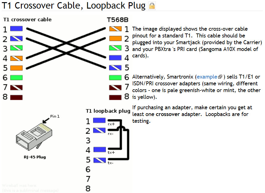
2 wire or 4 wire? Both line and wiring diagrams are a language of pictures. Pin outs for t1 cable and cross over cable.
Air flow rates and for use of line lengths over 15 feet. This is supported through 2 and 4 wire e & m (ear and mouth) signalling techniques through the t1 mux. G used for independent fan control only.
Wiring diagram book a1 15 b1 b2 16 18 b3 a2 b1 b3 15 supply voltage 16 18 l m h 2 levels b2 l1 f u 1 460 v f u 2 l2 l3 gnd h1 h3 h2 h4 f u 3 x1a f u 4 f u 5 x2a r power on optional x1 x2115 v. T1 t2 t3 t4 t5 motor lead wires. Right click on the diagram/key/fuse box you want to download.
Electrical symbols and line diagrams chapter 3 material taken from chapter 3 of electric motor controls, g. I think the standard is called t568c they are wired with the center 2 pins with the blue pair, and the orange pair on either side of the blue pair. Symbols are electrical representation only.
Print the wiring diagram off and use highlighters to be able to trace the circuit. The l symbol designation refers to the line, or the incoming circuit wires that provide the power for the motor. Correspondingly, what is l1 in wiring?
Bohack » Blog Archive » T1 / DS1 Smart Jack RJ48C Wiring Explained End to End

Cross Over Cable Diagram T1 E1 J1 Rj48 Cable Diagram Tbwiki Pin 2 on connector a goes to pin
RTU for Small, Outside (OSP) Site with Only T1 Available?
T1 Cable RJ48C and RJ48S RJ48X 8 position jack pin out for T1 termination by Bell
21 Awesome T1 Wiring Diagram Rj45


T1 Crossover Cable Pinout
How to make a T1 Crossover cable SH RUN

SpitFire Help Desk Wiring Diagram for Standalone SPD 24x48 T1/E1/PRI

T1 Wiring Diagram Wiring Diagram


T1 Wiring Diagram
T1 Wiring Diagram Pdf Complete Wiring Schemas

T1 Crossover Cable Wiring Diagram Wiring Diagram

Network Wiring How To Fryguy's Blog

4 Wire T1/E1 NEBS RLH Industries, Inc.
T1 Cable Pinout

T1 Wiring Diagram

T1 Wiring Diagram
T1 Wiring Guide Here's a pinout for a T1 circuit. It's pre… Flickr
[DIAGRAM] Rj45 T1 Wiring Diagram FULL Version HD Quality Wiring Diagram DIAGRAMMATICLYMCOQ
